Projects
8-Bit Breadboard CPU
Divider Design
In prep for final design, I built a divider as a warmup for similar circuits.
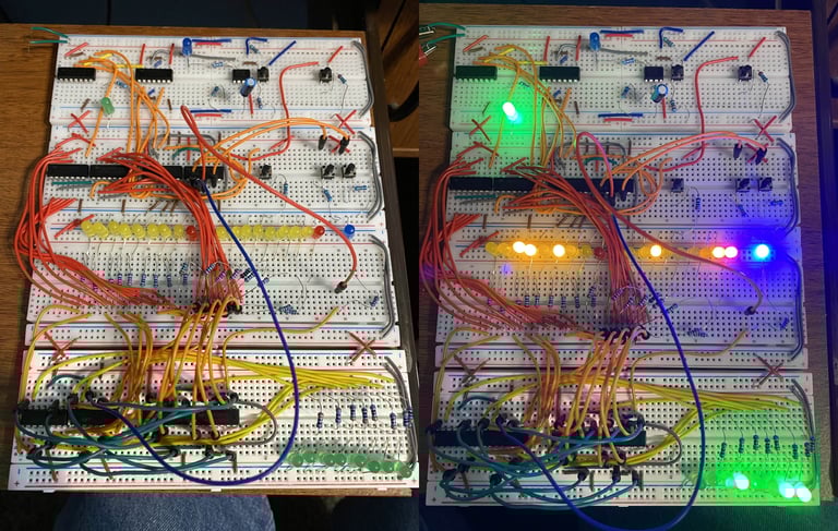
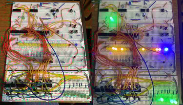
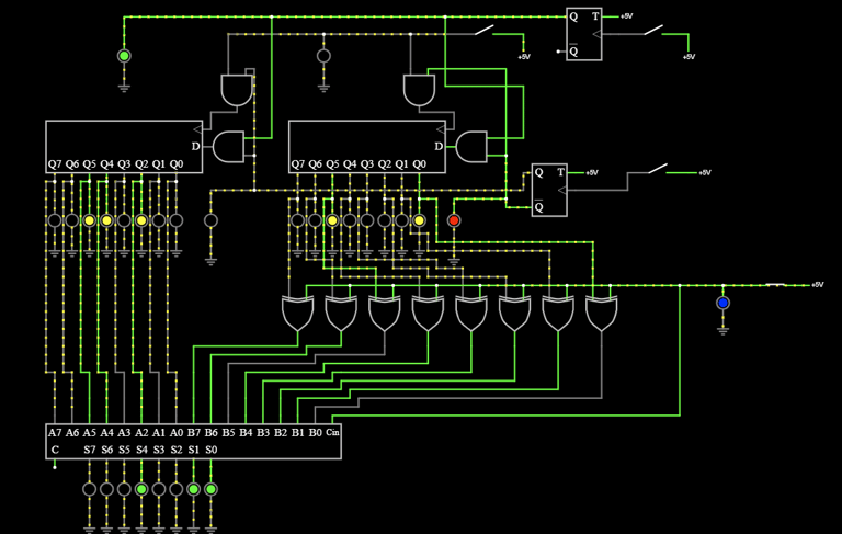
Serial Loading 8-Bit Adder & Subtractor
This is the final design of a practice circuit to get familiar with the circuit design. The first green LED is the bit being loaded in to either register. The red LED shows which register is selected. The blue LED Indicates subtract mode. The yellow LEDs are the registers, the left is register A and the right is B. The output is the bottom green LEDs and is the result of A+B or A-B (mod 255) depending on the mode.
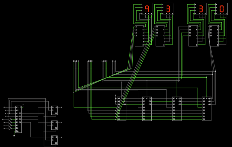
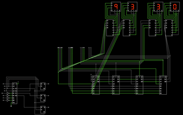
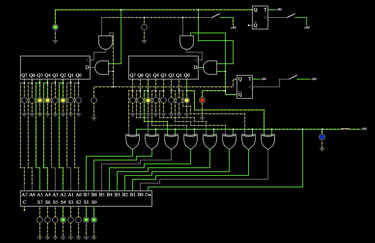
Serial Loading 8-Bit Adder & Subtractor Schematic
The schematic of the previous circuit.
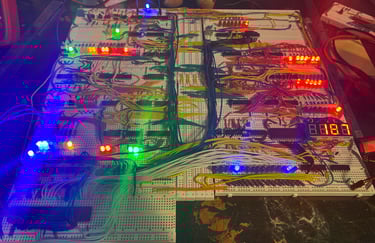
Final CPU design Before Bug Fixes
The final design built out without input fixes to allow bug fixes.

8x8x8 RGB LED Cube
Control Module (outdated)
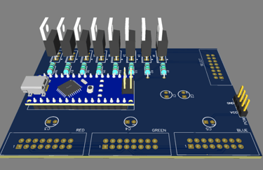
Powered by an Arduino Nano, uses IRF9540 Mosfets to invert select lines for the cube.
Shift register modules connect to the control module using 16 pin ribbon cables.
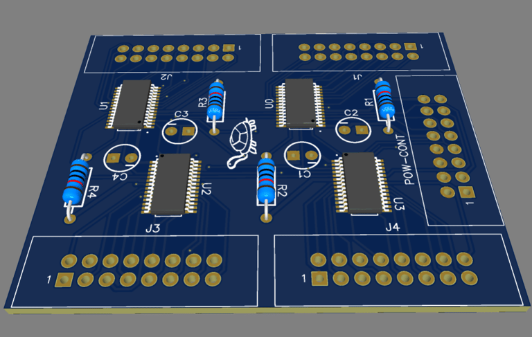
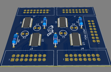
Shift Register Module (outdated)
Takes in the control instructions and power from the control board and outputs the 64 shift register outputs
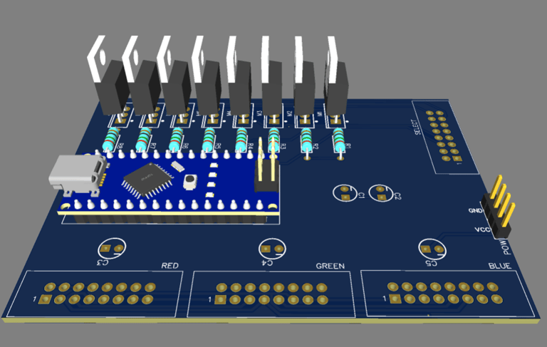
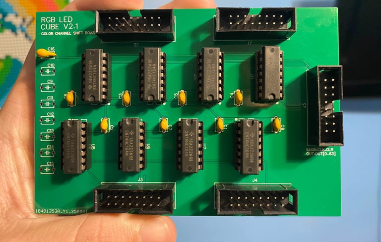
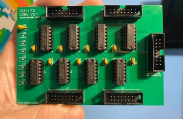
Updated Color Channel Board
The PCB was modified to allow significantly cheaper integrated circuits to be used with sockets. Components can now be swapped in the case of failure
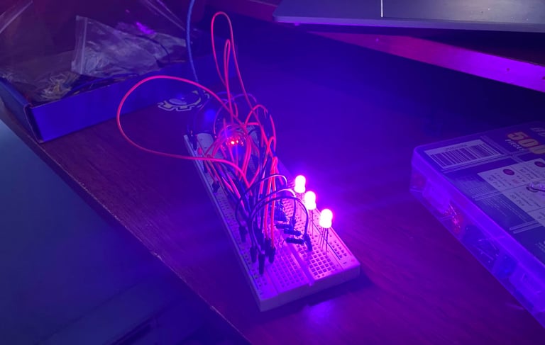
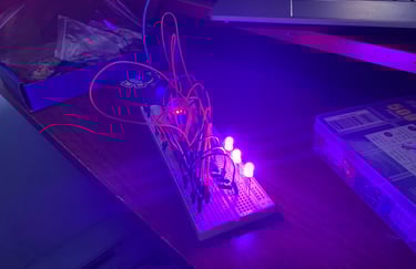
Testing LEDs
LEDs colors being tested using arduino nano. Each of the 512 LEDs have to be tested.
About Sean White
I'm a student raised and living in a smalltown in New York. I delved into writing at the start of 2024 to help summarize my mental development and stress over my life. I'm going to college for electrical engineering.